


The article source by NAPSON
Napson is the only vendor in the world, who manufactures and sells 2 kinds of resistance measurement equipment.
Contact types with 4-point probe and Non-contact types, such as eddy current measurement.
Here are the electrical resistance principles which can be measured by Napson resistance measurement systems.
Generally, electrical resistance (Resistance) is used as evaluation of the conductivity (Ease of electric conductance) of a substance or material.
“As a valuation basis of electrical resistance, the unit Ω(ohm)is used.”
The insulation resistance, for example, measured by a digital multi-meter (insulation resistance tester) is denoted by the unit, ohm.
The electrical resistance for a semiconductor or thin film measurement is defined by standards, such as SEMI (ASTM) and JIS.
[or Specific lectrical resistance, Volume resisance]
Resistivity is used for “volume resistance” for a substance.
When it expresses the electrical resistance of a certain material, such as a silicon wafer, bulk or a conductive rubber plastic, this term is used.
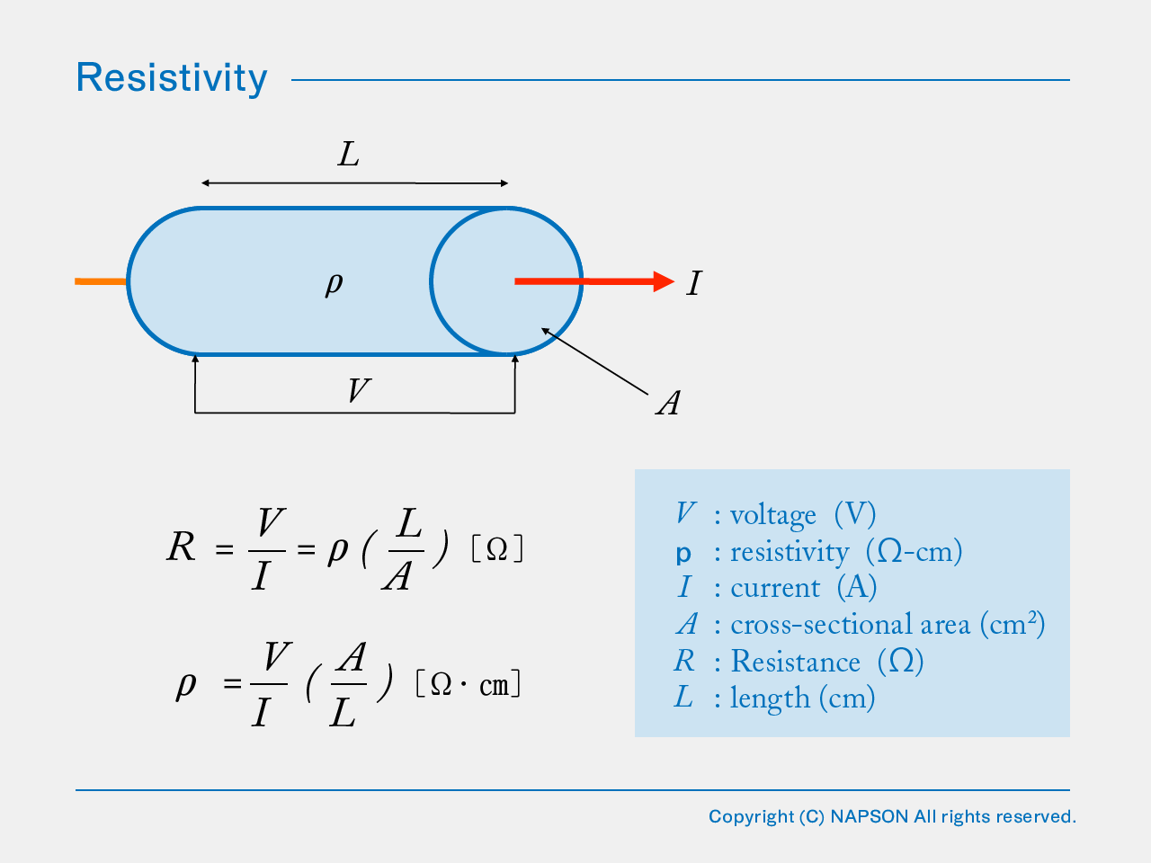
Electrical resistance: When the electric resistivity is ρ, the length is L and cross-sectional area for a conductor is A
The R is givin by ;
Where ρ is given by
*When the unit is set to Ω-cm, the volume is shown by cubic measure, such as 1cm x 1cm x 1cm.
It may be shown by Ω-m (ohm meter) depending on the measuring object.
The “surface resistance” for a material
When it expresses the electrical resistance of a sheet (such as a thin film or a film-like substance), this term is used.
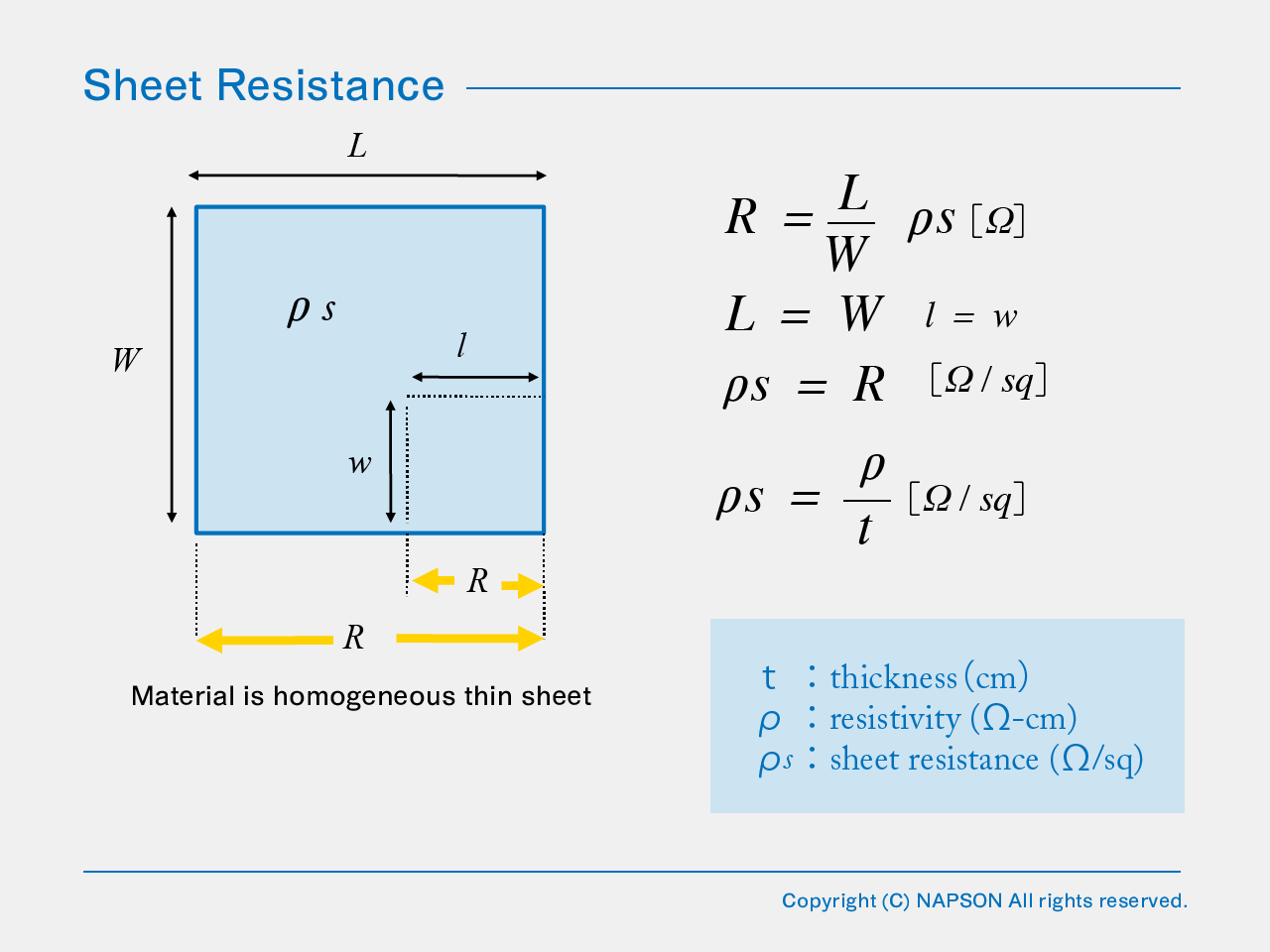
When it expresses three-dimensional conductivity, resistance is givin by
When the length of a sample[L] and the width[W]are equal, the resistance[R] and he sheet resistance[ρ] will become equal.
“Moreover, Sheet resistance[ρs] is the value which divided resistivity[ρ] by thickness[t] .”
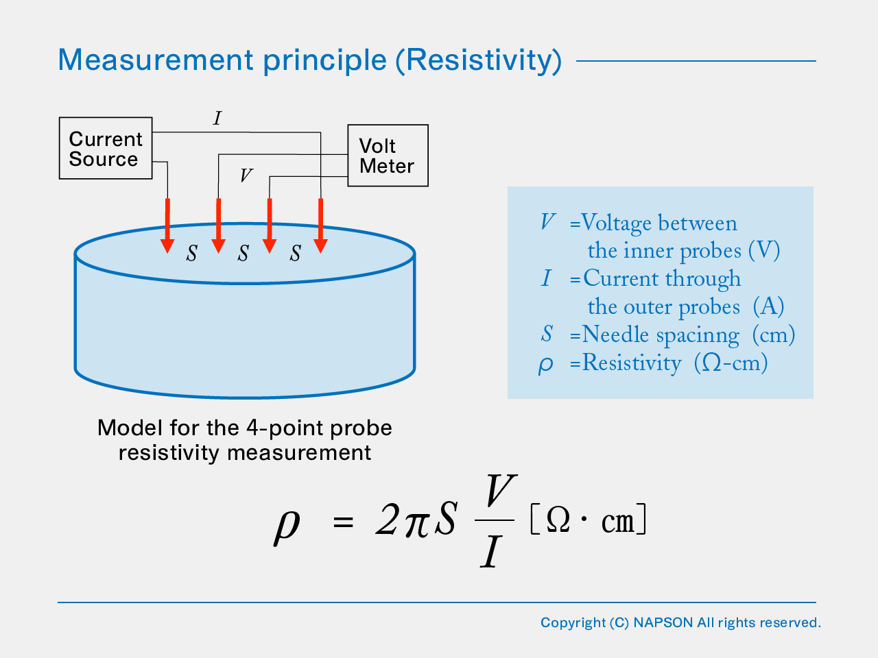
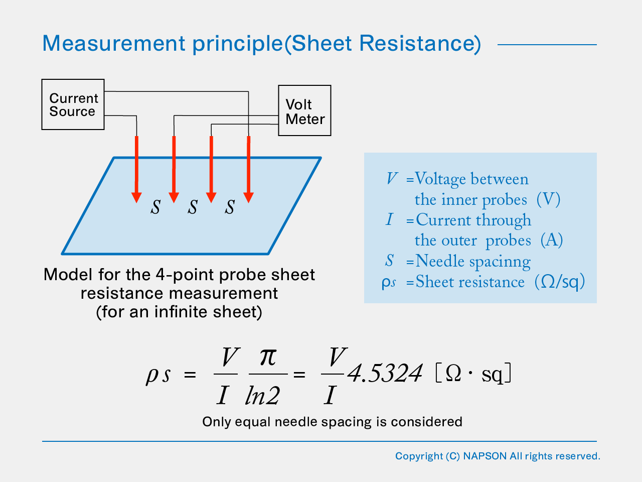
This describes the resistance measurement principle for a contact type (4-point probe measurement method)
Four metallic probe pins are applied to the surface of a specimen, being lined up, and current is made to flow through the two outer most probe pins.
When the difference in potental between the tow intermediate probe pins is measured , the resistivity ( or sheet resistance) can be found from the shown equation.
*Resistivity measurement & sheet resistance measurement are the same measurement principle.
4-point probe measurement systems made by Napson serve as a measuring method and the compensation method based on JIS and an ASTM(SEMI) standards.
This system is relied upon as an industrial standard measurement system by the silicon wafers/ingots related users in Japan and Asia.
Moreover, it provides traceability to NIST (National Institute Standard Technologies[USA]) standards and resistivity samples.
Instruments/ systems are shipped after calibratios and careful testing with standard samples at the factory.
The Napson 4-point probe method instrument complies with the following Japanese Industrial Standards (JIS)and American Society for Testing and Materials (ASTM).
This describes the resistance measurement principle for a non- contact type (eddy current method).
The non-contact type (eddy current method) performs measurement of resistivity and sheet resistance by using the eddy current which occurs by electromagnetic induction within a specimen.
An eddy current is circular current which forms in a conductor due to electromagnetic induction [Lenz’s law], when the magnetic flux which passes along a conductor changes.

The magnetic flux is changed by adding high frequency component between the probes (magnetic body), arranged on both
sides (upper and lower sides) between the fixed gap, where an eddy current flows through the sample inserted between gaps.
(*Napson can offer other models with one side probe version)
At this time, an eddy current flows into the direction which resists change of the magnetic flux by electromagnetic induction [Lenz’s law].

Pc : High-frequency consumed power I : High-frequency drive current Et : High-frequency voltage
Io : High-frequency drive current [Without sample] Ie : High-frequency drive current [at the sample measurement]
The absorption of high-frequency power in the sample by the generated eddy current is lost as Joule heat.
The resistivity/sheet resistance of the sample can be measured with the non-contact method by measuring the absorption value of high-frequency power,
because this absorption and the conductivity (reciprocal of resistivity) and thickness of a sample have a direct relationship.
(*The Joule heat is so small that neither the sample nor the area is affected.)
Moreover, the influence of contact resistance in the case of a contact type can be eliminated.
Explanation of Non-contact (Dual probes ) and Non-destructive(Single probe)
As mentioned above, the resistivity ( or sheet resistance) is measured by inserting a sample in the gap between the probes.
Therefore, restrictions on the form of a probe depend upon the thickness and corresponding size of a sample.
– Restrictions of the thickness of a sample : the gap between probes is usually 2 mm.
– Restrictions of the size of a sample :A large specimen has a limit on the measurement head.
Napson offers the technology of a single sided and hand probe to measure a big or thick sample with a simple and easy operation as shown below.

[Non-destructive(Single probe) type system : EC-80P]

